Swift
| Type: Size: Usable range: Sensitivity: Continuous max SPL: Est. build cost: | Single driver, vented Very small stand-mount/bookshelf 60 Hz-20 KHz (in-room) 87 dB / 2.83 V / 1 meter 103 dB (pair, 1 meter, from 60 Hz) 200-250€ |
Introduction
This project was originally a Christmas gift for my little sister, who listens to a lot of music but unfortunately not through anything that does it any justice. So I thought I would build her some small, competent and slightly girl-ish speakers! The problem was... they sounded too good. So I kept them for myself.
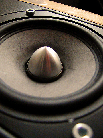
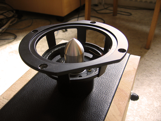
The design originated from the driver. The Tang Band W4-1320SA (now 1320SD) was chosen mainly for its fashionable appearance. With a pretty bamboo-fiber cone, solid cast chassis, an under hung neodymium motor with copper in the gap and a solid aluminum phase-plug that makes Baby Jesus cry; this driver is as well designed as it appears to be. It's hardly expensive, but it looks and sounds like it would be.
Note: I used the version of the driver with cut flanges on the sides, so the baffle became thin to match it. If I could have gotten my hands on the round-chassis version I would have preferred it, actually, because routing none-round cutouts is no fun. If you have the non-faceted frame drivers, see notes on the cabinet dimensions below.
Cabinet
What we have here is about 5.5 liters, ported and tuned around 70 Hz via a slot port integrated into the enclosure.
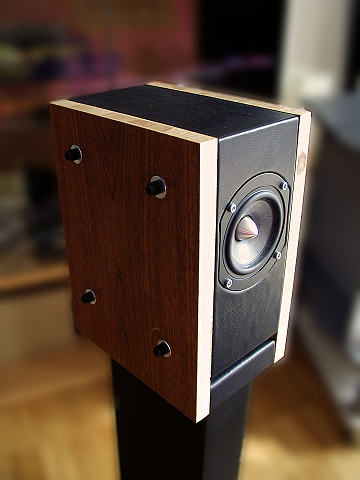
The construction plan shows how to build the "center" part of the speaker on which the sides will be put on.
The sides can be whatever material you want, for example, I put leather around the main part and used some hardwood side panels bolted together with everything pressed in between. It made for one helluva solid cabinet and with the added bonus of being able to disassemble and assemble as much as you like.
Click for larger size.
The sides would be 320x240 mm and about 15-20 mm thick. For great justice you could round over the outer vertical edges of the sides (for smoother diffraction).
The port is 12 mm high and about 14 cm long. Notice the 12,7 mm or half-inch round overs at the port exit. This radius can be a bit smaller with no adverse effect, in case you lack the right router bit. I admit it is mostly cosmetic.
As for filling, I used a piece of synthetic anti-reflect patterned foam on the rear wall and above the driver. For a slacker fall-off and a wee bit more extension (say, near a corner) you could use more, softer filling such as natural wool or something synthetic.
I also covered most inner surfaces, excluding the port area, with 4 mm thick bitumen pads. This also provides a stable surface to put the filter components on. They will kind of naturally stick to the bitumen by their own weight.
Something else that I recommend is to chamfer the inner opening of the driver cutout, for better airflow. Use a small round over router bit to do this, but save some wood around where the T-nuts and screws will go.
Important note: If you have the version of the driver with the round chassis and want to build this design, you can still do it. How much you need to change depends on how you will build it. If you intend to use separate side panels as I did, you need to make the center cabinet part 15 millimeters wider and 20 millimeters less deep. You will need to adjust your parts diagram yourself, but just keep in mind that the port length shouldn't change and only the total width and depth of the whole cabinet. This will make the port throat opening a bit smaller but the effect is negligible. The baffle will now have room for the full round cut-out (125 mm).
However, if you will build the whole thing as a solid part with the sides glued on, you can just keep the original width + the sides and route into the sides to fit the whole round driver.
Crossover
Not so much a crossover as some equalization and impedance compensation. No need to get complicated with these drivers.
The final filter I used. Even if you vary the baffle size +- a centimeter or two this would still work. Just don't place the driver any differently. You could get a flatter response with a few notches but having more stuff in the signal path would take away the "full range" driver benefits. Use air-core inductors and metal oxide resistors. The biggest cost here is the inductor. | 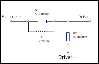 |
IMPORTANT NOTE: The new version of the driver, the W4-1320SD, has a new and improved frame and while you might think it has changed, the dimensions, parameters and response is 100% identical. If you have the new version of the driver you can still use the same enclosure and filter. This driver also exist in a faceted and a round version.
Decent sensitivity at 2.83 volts. A bit ragged top end but there is no harshness what so ever with these drivers.
The impedance and electrical phase will not pose a problem for, well, anything.
Conclusion
The end result was great. They definitely sound good, and the bass was surprisingly potent and well-defined. You can use them without additional bass-support for sure. Just place them a bit closer to a back wall. Now, they are no reference monitors. They do paint a beautiful picture, albeit not necessarily a realistic one. I would still call them neutral though, not really favoring any kind of music genre, doing a good job with all of them.
They can take some punishment and play fairly loud before distortion sets in due to the coil traveling outside the gap. The linear Xmax is a well generous 6 mm p-p, and this is what will limit you. I have tried everything from a T-Amp (not bad, but not loud either) to an integrated Rotel up to my current Behringer A500 which works like a charm.
The ultimate verdict: They would fit best for smaller rooms. Personally, I used them as my main speakers in my fairly large living room (58 cubic meters) and I could not really complain considering their size. Either way, they're cheap, they're good, and they're easy to build. If you are looking for a good first project, this might just be the one for you.
I also had the chance to hack one driver to pieces when it failed due to a small metal fragment getting into the magnetic gap. Behold!
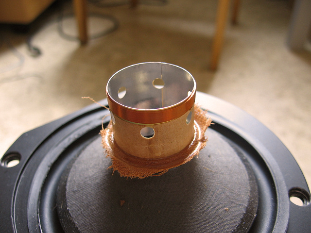
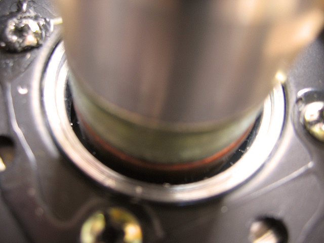
As you can see the voice-coil is very small but that's under hung for you. It's really the only way to get good excursion on a full range driver that needs to maintain a low moving mass in order to produce the highest frequencies.
The copper sleeve reduces the already low inductance and improves linearity. The clearances in the magnetic gap are extremely tight and much better than I have seen on any expensive phase-plugged driver such as the Seas Excels. Pretty cool.
R.I.P.